The Blind Rivets : technical datas
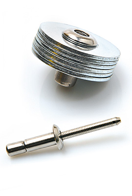
The rivet body

The rivet mandrel

The print of the mandrel is stamped with a tool consisting of four tungsten carbide jaws, designed, developed and manufactured within the research department of 4F company.
The 4-jaw technology

- Ensure a constant tensile strength of the mandrel.
- Ensure a clear and precise mandrel breaking point.
- Obtain the special dimensional and mechanical for developing specific products.
Installation description

Blind rivet installation requires a special tool.
This tool can be manual, hydro-pneumatic or with a battery depending on the type of rivet and application

How to choose the right length for a rivet*
Add at least 1 time the diameter of the body to the thickness of the parts you want to crimp.
EXAMPLE :
You need a rivet with a 4,8 mm diameter to crimp metal sheets whose total thickness is a 6 mm.
The minimum "L" length under the head of the rivet will be 6 + (1 x 4,8) = 10,80 mm. – In theory, choose a 4,8 x 11 or 4,8 x 12 rivet.
* This is only valid for the standard rivets.
Domed Head

Countersunk Head

Large Head

Extra Large Head

Dimensional Characteristics
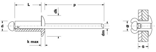
| Ø d (mm) | Diameter of the body |
| Ø dk (mm) | Diameter of the body's head |
| k (mm) | Thickness of the body's head |
| L (mm) | Lenght of the body |
| p (mm) | Protrusion of the mandrel |
| Ø d (mm) | Diameter of the mandel |
 |
Drilling diameter (mm) ø |
 |
Grip range (mm) S |
 |
Tensile strengh (N) |
 |
Sheer strength (N) |
Mechanical characteristics

Tensile strength is the capacity of a rivet to resist forces pulling axially on it (value expressed in Newton).
Shear strength is the ability of a rivet to resist forces acting parallel to the application surface, tending to cut it (value expressed in Newton).
1 kg = 10 N
Clamping curve

Clamping strength corresponds to the fastening effort between mechanical elements.
This characteristic is not standardized and depends on various parameters intrinsic to the rivet, ensuring its optimum functioning.
General tolerances
These dimensional tolerances are valid for our NF-E 25-701, NF-E 25-702 compliant rivets.
We can also supply DIN 7337 compliant rivets.
| Ø NOMINAL | 2,4 mm | 3,0 mm | 3,2 mm | 4,0 mm | 4,8 mm | 5,0 mm | 6,0 mm | 6,4 mm | |
|---|---|---|---|---|---|---|---|---|---|
| d | 2,30 - 2,48 | 2,90 - 3,08 | 3,10 - 3,28 | 3,85 - 4,08 | 4,65 - 4,88 | 4,85 - 5,08 | 5,85 - 6,08 | 6,25 - 6,48 | |
| dk | TRS | 4,2 - 5,0 | 5,4 - 6,3 | 5,8 - 6,7 | 6,9 - 8,4 | 8,3 - 10,1 | 8,7 - 10,5 | 10,8 - 12,6 | 11,6 - 13,4 |
| TL | 7,0 - 8,0 | 9,0 - 10,0 | 13,0 - 15,0 | ||||||
| TEL | 9,0 - 10,0 | 11,0 - 13,0 | 15,0 - 17,0 | ||||||
| TF | 4,2 - 5,0 | 5,4 - 6,3 | 5,8 - 6,7 | 6,9 - 8,4 | 8,3 - 10,1 | 8,7 - 10,5 | 10,8 - 12,6 | 11,6 - 13,4 | |
| TR | 6,0 - 7,0 | 7,5 - 8,5 | |||||||
| k max | TRS | 1,0 | 1,3 | 1,3 | 1,7 | 2,0 | 2,1 | 2,5 | 2,7 |
| TL | |||||||||
| TEL | 1,3 | 1,7 | 2,0 | ||||||
| TF | |||||||||
| TR | |||||||||
| p min | 25 | 25 | 25 | 27 | 27 | 27 | 27 | 27 | |
Cold forming

Cold forming is a shaping process through which materials are deformed without pre-heating. The machine crops a blank from a wire, then deforms it successively until it reaches its final shape; these extremely fast deformations (just a few hundredths of a second) occur in general either by pressing between a punch and a die, or by creeping around an extrusion punch along the inside of a die. In this way, solid, semi-tubular, tubular or specifically shaped parts can be formed.
Cold forming provides finished or almost finished parts that present excellent mechanical properties. Grain flow orientation is created by the sudden deformation of the material. This process provides very high production rates (up to 500 parts per minute) with minimum waste.
Today, thanks to greatly improving techniques combined with finite element simulation, increasingly complex mechanical parts can be created via cold forming
Surface treatment, Electrolytic Zinc
and Black Iron Zinc Plating

Surface treatment WITHOUT CHROMIUM VI is applied to the body of steel and CuNi alloy rivets as well as steel mandrels. The thickness of the coating varies and depends on the desired resistance to corrosion. Standard thickness is 3 to 5 microns, but greater thickness can be requested.
Zinc Nickel Plating
Surface treatment WITHOUT CHROMIUM VI is applied to copper and CuNi alloy rivet bodies. It is used when a rivet must have a very high resistance to corrosion
Anodization
This treatment corresponds to a coloured protective coating on aluminium bodies to protect them significantly from air exposure.
Lacquering
The colouring can be done on any type of body. The choice of colours is almost unlimited: classic colours, all types of special and RAL colours on request.
Electrolytical reaction
When the 2 materials are in contact, corrosion speed may change as indicated below:
| * | No risk of accelerated corrosion |
|---|---|
| ** | Small risk of accelerating the corrosion |
| *** | Most probable accelerated corrosion |
| **** | Dramatically accelerated corrosion |
| NICKEL- CUIVRE |
CUIVRE | LAITON | CUPRO NICKEL- ZINC |
INOX (A4/A2) |
DURALUMIN | ACIER | ALU | DURALINOX | ZINC | |
|---|---|---|---|---|---|---|---|---|---|---|
| NICKEL-CUIVRE | - | * | * | ** | ** | ** | ** | *** | *** | **** |
| CUIVRE | * | - | * | * | ** | ** | ** | ** | ** | *** |
| LAITON | * | * | - | * | * | * | ** | ** | ** | *** |
| CUPRONICKEL-ZINC | ** | * | * | - | * | * | * | * | * | ** |
| INOX (A4/A2) | ** | ** | * | * | - | * | * | * | * | ** |
| DURALUMIN | ** | ** | * | * | * | - | * | * | * | ** |
| ACIER | ** | ** | ** | * | * | * | - | * | * | ** |
| ALUMINIUM | *** | ** | ** | * | * | * | * | * | * | ** |
| DURALINOX | *** | ** | ** | * | * | * | * | - | - | ** |
| ZINC | **** | *** | *** | ** | ** | ** | ** | ** | ** | - |